Homemade Multi-zone Overspeed Alarm
(images, code, schematic at the bottom)
A friend of mine recently avoided loosing their license by the skin of their teeth after being caught speeding. Why were they speeding? Simply because they had been travelling along a long straight road for a long time and their speed had crept up slowly without them noticing it.
Usually the penalty for an offence such as this is loss of license and taking a backward step in our graduated license scheme; having recently obtained my P1 (probationary license), I have no desire to go back to the learners permit because I unintentionally crept over the speed limit, so I decided to make an overspeed alarm.
Overspeed alarms are useful devices that notify you when you cross a user defined speed limit, which is usually set in increments of 5km/h. Generally overspeed alarms come fitted in newer cars (ours is a 1998 Ford Falcon AU), however, kits are available to add them to older cars.
Looking around the net, it appears most overspeed alarms cost about $50 and require fitting of a sensor and magnet to the chassis and axle and routing of wire behind the dashboard. These speed alarms are only capable of one speed setting at a time and require you to jackup your car to attach them, so I decided to try my hand at making my own that I could fit to the existing wiring in the car, would not require an additional sensor and could allow multiple speed settings.
I looked around the internet once more to see if it had been done by anyone else before, my results turned up no similar projects, though I did find a well documented DIY digital speedometer, which I looked over to see if it worked on the same principal that I was planning to use.
The plan
- Allow multiple speed zones to be set
- 50km/h (built up areas)
- 60km/h (main roads)
- 80km/h (arterial roads and middle of nowhere roads)
- 100km/h (freeways, expressways, country)
- 110km/h (freeways, expressways, country, national speed limit)
- Provide a means to calibrate the device
- If the national speed limit is exceeded, continuously sound the alarm
How it works
The car contains a Vehicle Speed Sensor, which is located in the transmission and connected to the output shaft. The VSS is basically a 12v hall effect sensor and a spindle with a magnet on it; a gear turns the spindle causing a square wave (pulses) 0v – 12v DC. On our car there are 12 pulses per revolution of the wheels.
These pulses are counted over a time period of 1 second and the speed determined.
To count the pulses and calculate the speed I chose to use a PIC 16F88 (that’s all I have on hand at the moment), however a PICs maximum input voltage is 5V, which creates a problem.
Looking over the repair manual I discovered that the VSS signal goes to the instrument cluster, where the voltage drops to 10v and is then sent to the ECU; this is still too high but is easier to manage.
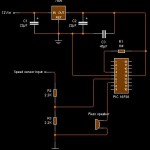
The trick to converting this unusable voltage to a more workable voltage is to setup a voltage divider that will give us an output of 2.5v – 5v when the the signal line is high and <2.5v when the signal line is low. The voltage divider was constructed using two 2.2kΩ resistors. Originally I had used a a 120Ω and a 150Ω resistor, however the current passing through these was too high and as a result, was loading the signal line (causing the voltage to drop to 1v instead of 10v).
The output of the voltage divider is connected to RB0 (pin 6), which is an external interrupt pin. When the interrupt triggers, a variable holding the number of pulses is incremented.
By knowing the circumference of the wheel (~196cm) it is possible to calculate that there are 510.2 revolutions of the wheel in 1 km. Since we also know that there are 12 pulses per revolution, we can deduce that there are 6122.45 pulses/km. If you are travelling at 1km/h there will be 102.04 pulses per minute or 1.70 pulses per second.
Knowing this, we can calculate how many pulses occur at each of our selected speeds.
A timer was setup to count in 1 second increments – this is no easy task, so I borrowed some code from Roman Black – when the 1 second interrupt fires, the code checks how many pulses have been recorded and if necessary sounds the alarm and then resets the pulse count.
ToDo
Add in calibration code. This will work by taking 10 samples over 10 seconds at 50km/h and calculating the average number of pulses at 10km/h
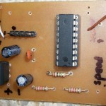
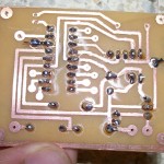
Schematics, Code, Images.
Source code – written in MikroBasic
Alarm tone – recording of the alarm
Disclaimer:
This information is provided ‘as-is’ without warranty of any kind. I take no responsibility for what you do with this information.


